The bowl feeder needs to vibrate with just the right frequency and amplitude in order to move the beads the optimal way. Since I don’t know the optimal parameters yet, I want to make a control circuit that allows me to tune frequency and amplitude of the vibration. In more technical terms this means I need two control knobs, two displays and a microcontroller for generating a PWM signal.
Since this project is about building a machine that sorts perler beads and not about designing an electronic circuit, I plan to use completed components as much as possible. There are complete microcontroller boards, LED drivers and 7-segment display-encoders out there, it makes no sense to build these things myself. I can really recommend Adafruit, they have lots of high-quality components for the electronic tinkerer!
Here is what exact components I chose:
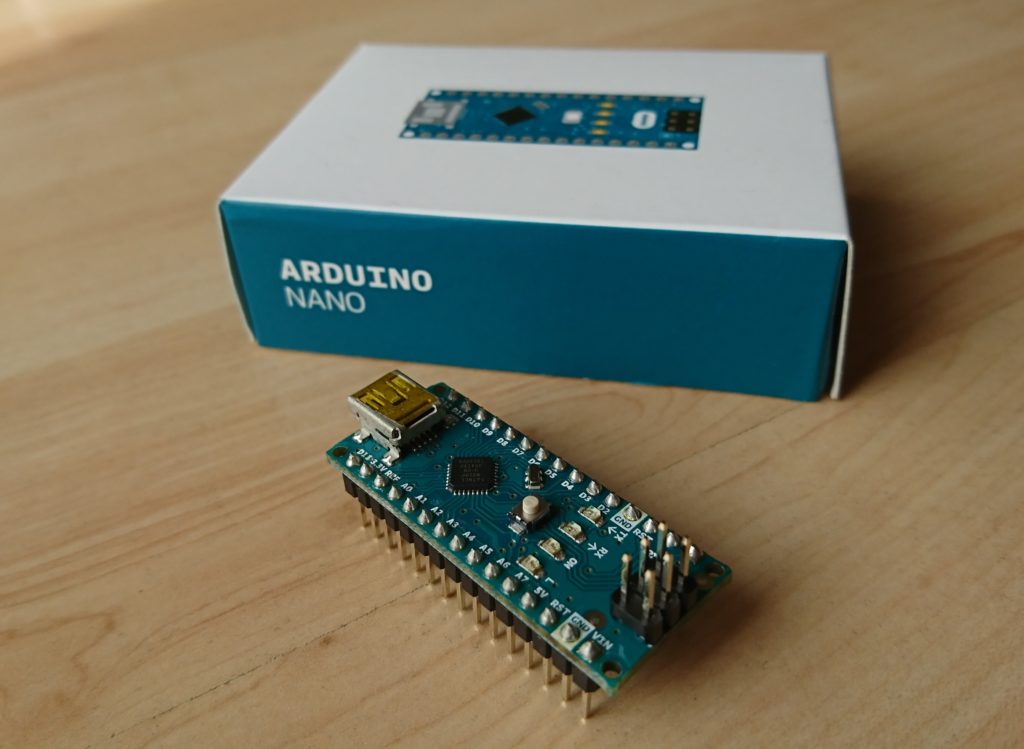
Arduino Nano microcontroller 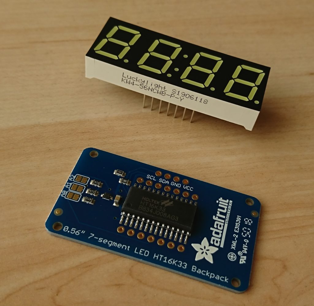
7-segment display with driver 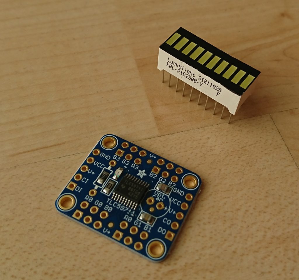
LED bar with driver
- The Arduino Nano is a rather small microcontroller, all it basically needs to do is generate a PWM signal. But since a microcontroller can do so much more than just generate a PWM, I let it also visualize the frequency and amplitude on two LED displays.
- The Adafruit 0,56″ 4-digit 7-segment display comes complete with a driver board that handles controlling the LED segments and can be connected with a simple I²C interface.
- For controlling the LED bar I also need a driver board. Firstly it would use too many CPU pins and secondly the CPU cannot supply enough current for all 10 LED segments. As driver board I bought the Adafruit 12-Channel 16-bit PWM LED driver. It can be controlled with a simple 2-wire SPI connection.
Update 2019-10-29: Finally, all pieces have arrived! In the meantime, I created the schematic. I decided to use Fritzing for that, one reason being that I was interested to learn it because it is a simple software that also my kids might use in a few years, and the other reason being that it supports prototyping on perfboards (hole-grid).
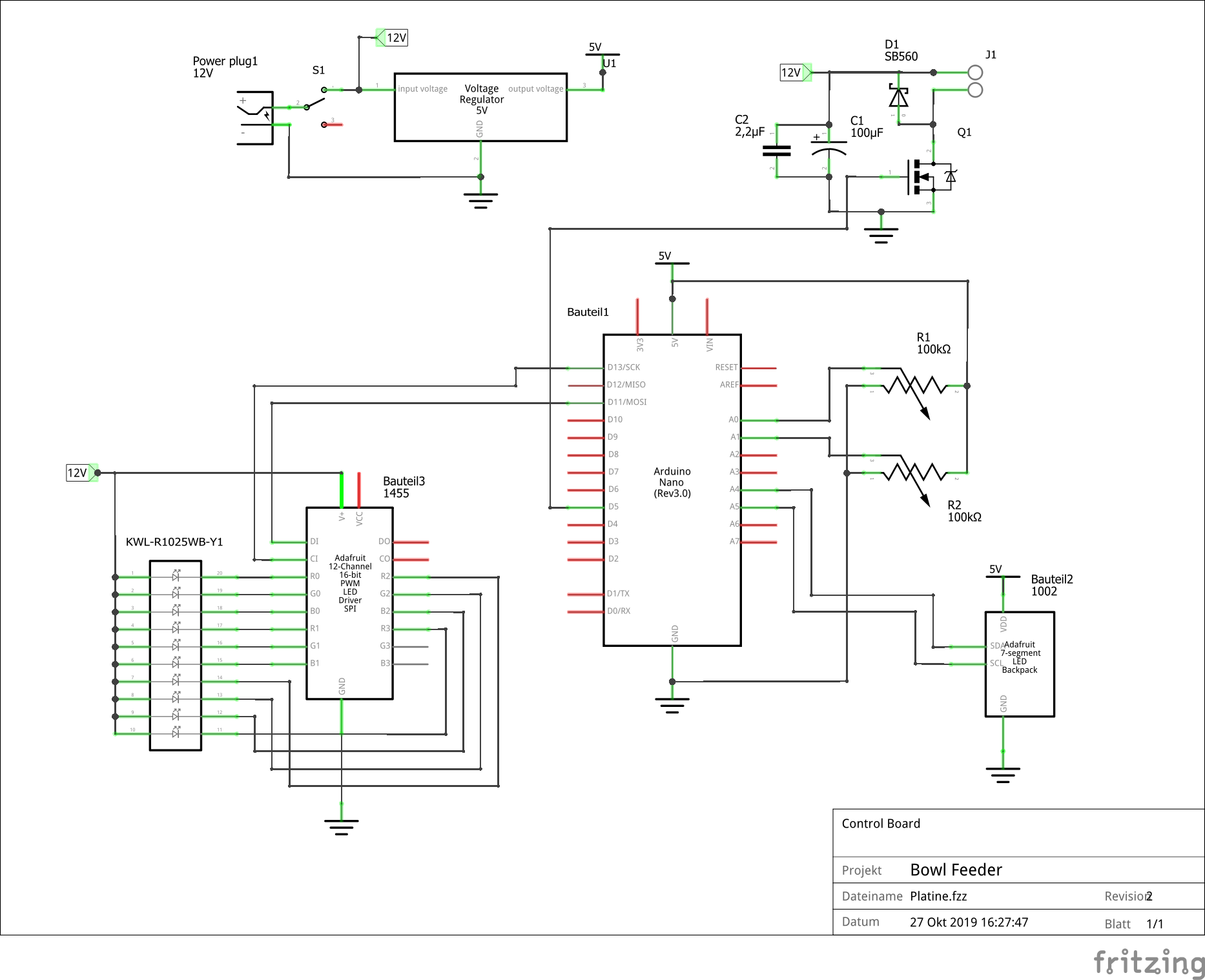
At first, I thought I can use the Arduino’s on-board 5V regulator to power the whole circuit. While it might actually be possible (it has an LM1117 that can provide up to 800mA) I decided to use a separate regulator to be on the safe side. At Conrad I found the W78-5V0 which will be just fine.
While the 7-segment display needs exact 5V, the PWM-driver for the LED bar can work with anything between 5-17V. I chose to connect it directly to 12V in order to have less losses.
I did tests with the electromagnets to find out which voltage they need. At 5V there hardly was any magnetic attraction noticeable, with 12V it was fine and with 15V they started to get quite warm. That’s why I’ll power them with 12V. Their power will be switched on and off by the Arduino’s PWM signal, for this I use an N-channel MOSFET. I found a nice and cheap model on Adafruit: the TRLB8721. I also added two capacitors to support the supply voltage and, most importantly, a fast protection diode that dissipates the induced current that appears when the magnet’s supply is cut.
Update 2019-11-01: I made an approximate perfboard layout with Fritzing. I’m not too proud of it though – while Fritzing does support perfboards better than other programs (Eagle for example), it’s still far from perfect. There is no way to enter connections on the copper side of the board, that’s why I had to connect the wires directly to the component pins:
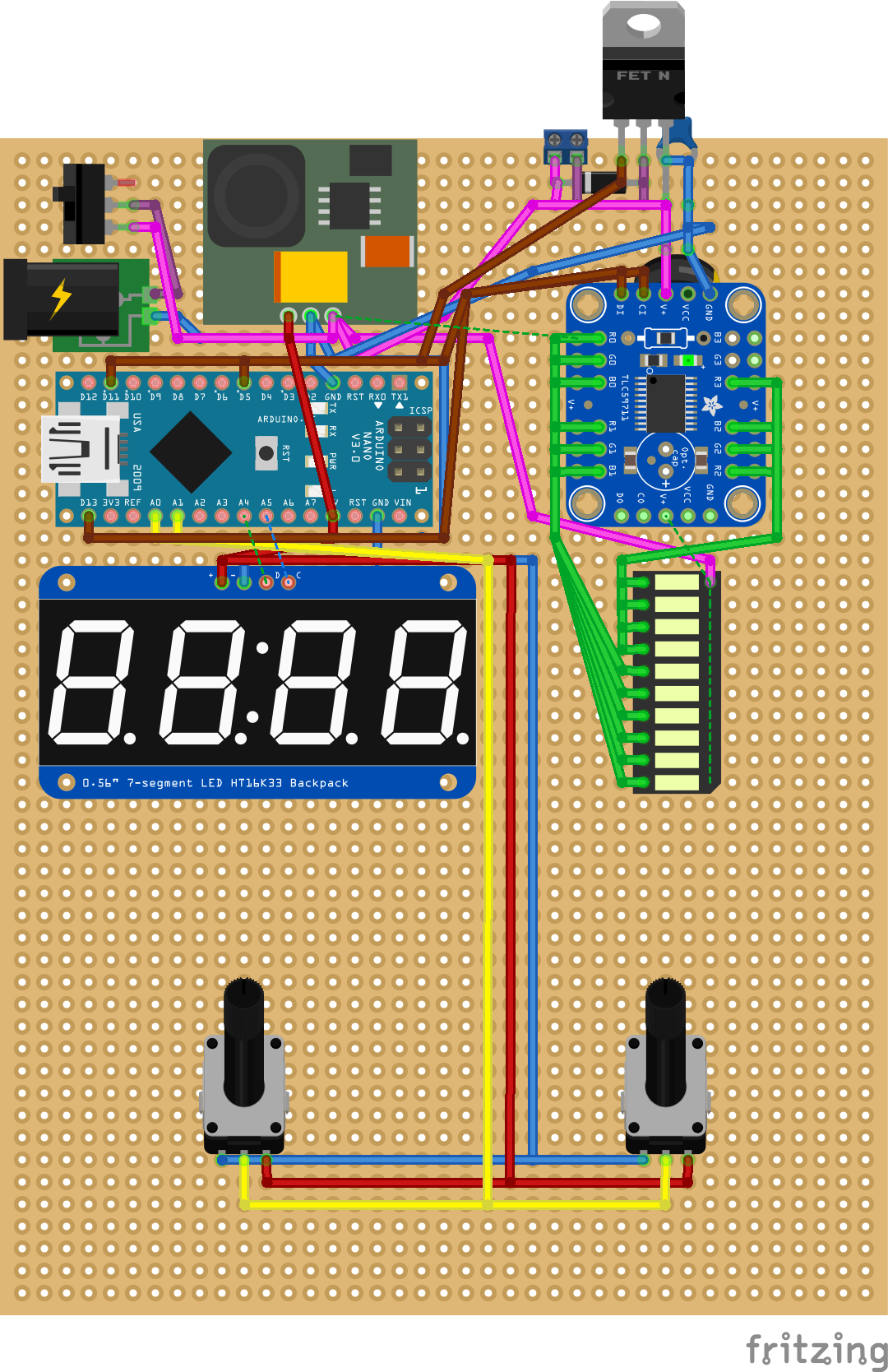
On this picture you can also see that Fritzing has a few problems with the perfboard: for example, the two capacitors next to the MOSFET are barely visible.
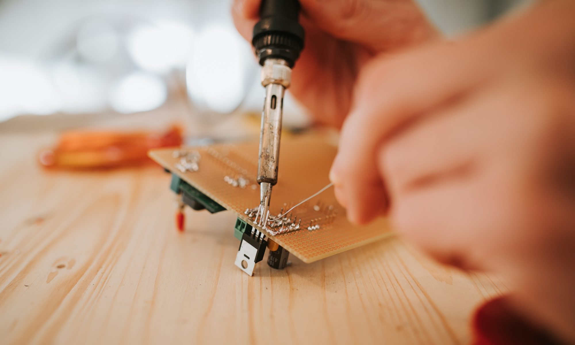
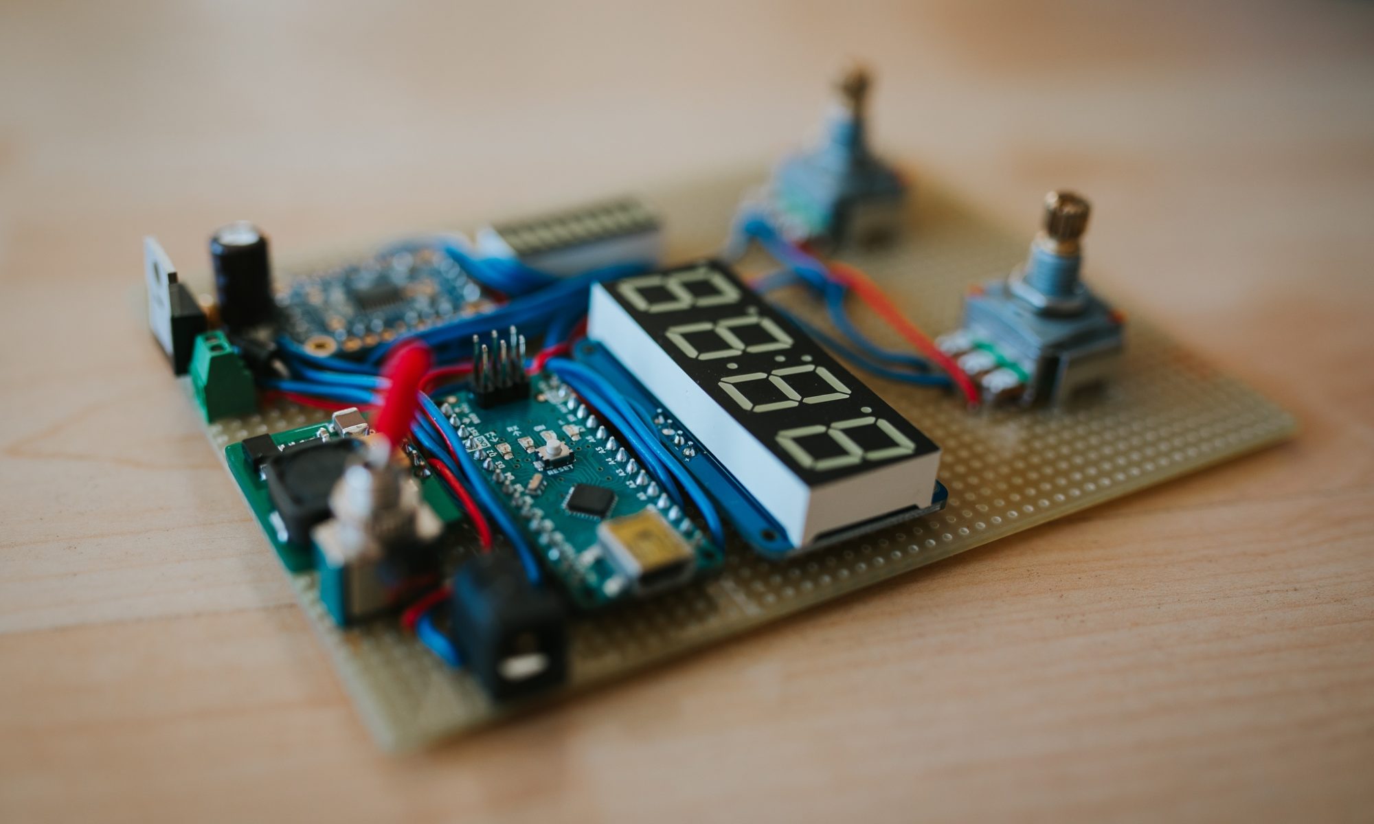
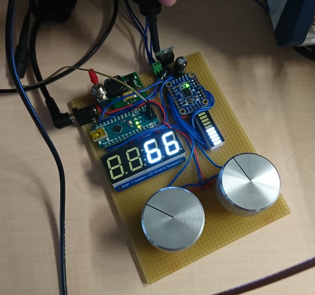
Update 2019-11-03: I finished the soldering! I could make the connections almost exactly as designed in Fritzing. I only turned the potentiometers around to have shorter cables.
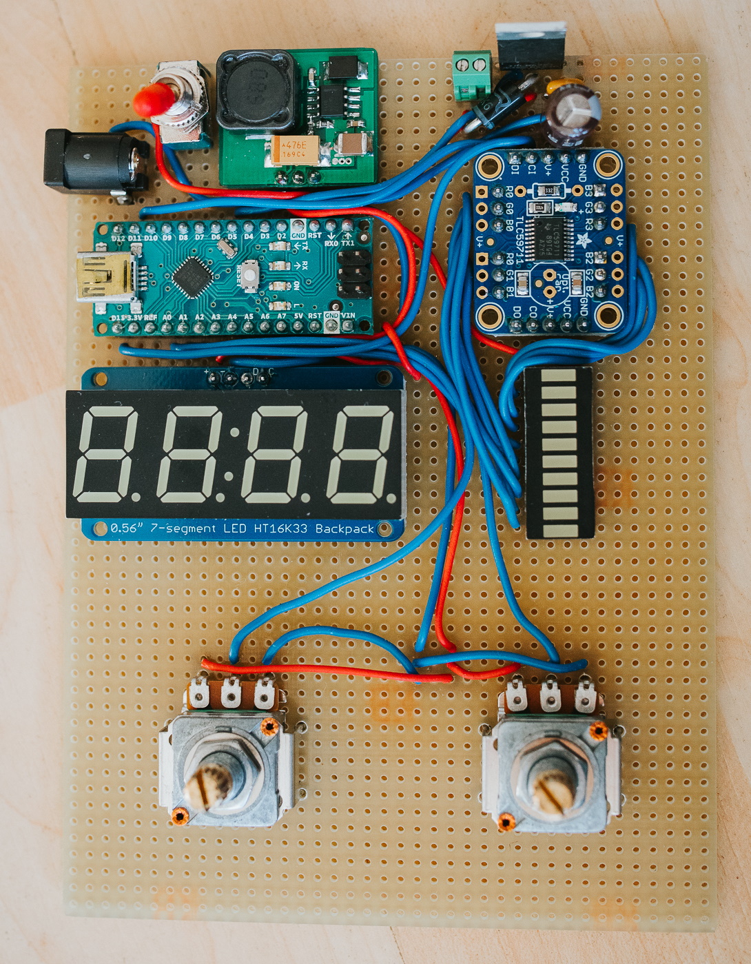
I ran two test programs (Arduino examples) to make sure the 7-segment and the LED bar are connected correctly. Funny thing is, I immediately found a problem in my schematic: If I have connected the Arduino via USB to the computer and switch off the board’s power switch, then current could reversely flow into the voltage regulator and damage it. To avoid that I could put a diode on the regulator’s output. I would also have to change the 12-channel PWM driver from 12V supply to 5V, otherwise the SPI lines from the CPU could be 5V higher than the driver’s VCC, which could again damage the component.
I’m not sure if I will change my board or leave it as it is. After all, it won’t be connected to a computer very often, only during software development. And since it doesn’t need much software, this won’t be long. My next post will discuss the control software, stay tuned!
Update 2019-11-13: I almost finished the control software (will show you in my next post), but during implementation I noticed I need a small hardware modification: Originally I planned to use the fastest PWM, timer 0, which controls pins 5 and 6. That’s why I connected the MOSFET to D5 in my schematic above.
I thought I’ll constantly change the PWM’s duty cycle to obtain an analogue voltage that follows a sine wave. While this is possible in principle, I think it’s rather slow and not a very elegant solution. I had a much more elegant idea (which I’ll not tell yet 😉 ), but this will be a bit more effort to implement.
Anyway, I wanted to test the vibration and my mechanic setup, not start a new project! So I took a shortcut and simply generated a square wave signal, in other words, just switch on and off the electromagnets with the right frequency. For this, I needed to change the PWM frequency too, not just the duty cycle. And since timer 0 also times all other Arduino functions, I would mess these up. So I decided to use timer 1, which meant I had to do some soldering and connect the MOSFET to D10 instead of D5.
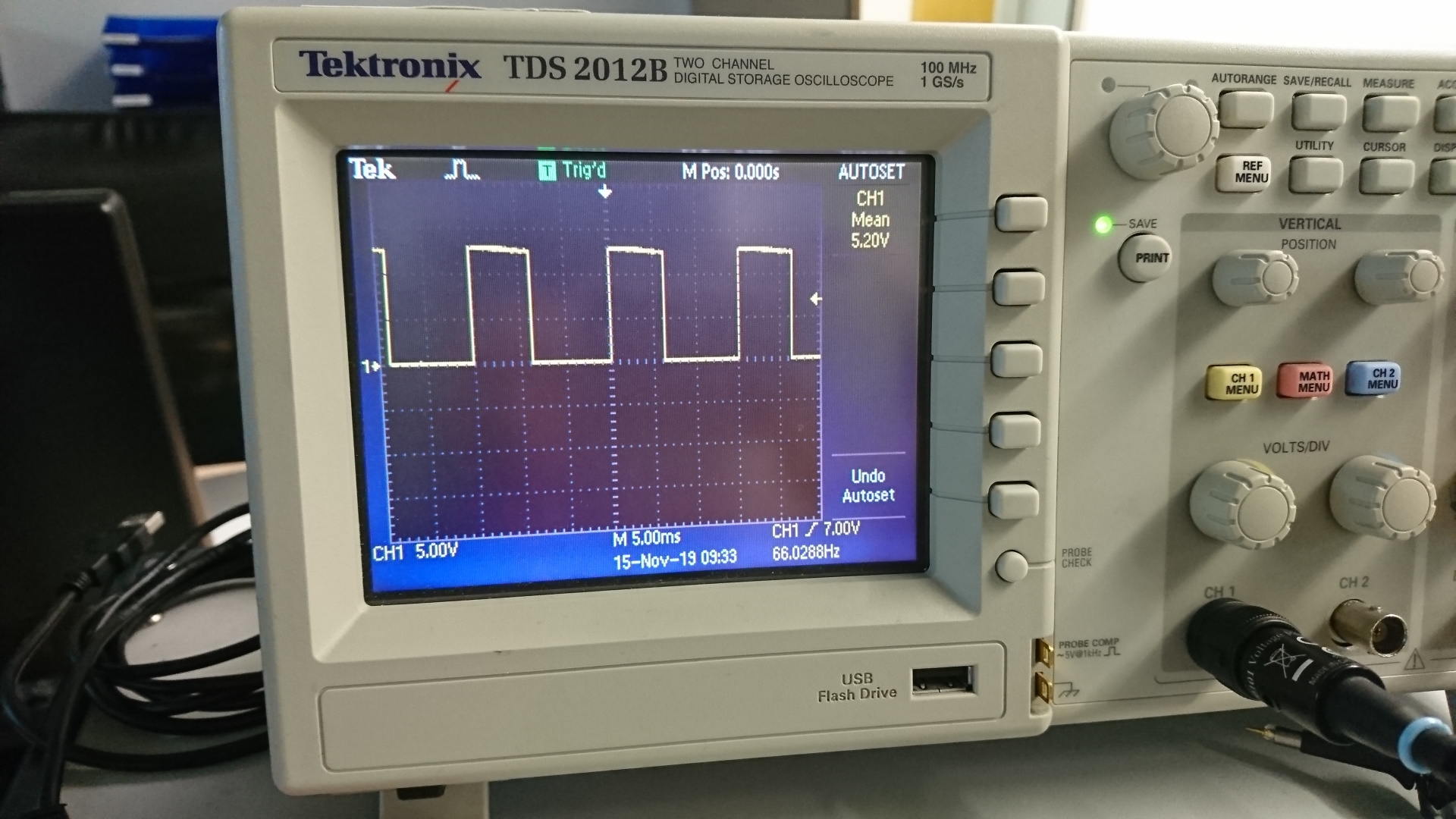
Update 2019-11-15: Today I tested the resulting PWM signal with a scope and I must say, I’m very pleased. Not only is the frequency exactly what the display shows, also its duty cycle is just how it should be:
One more thing that I learned today: Always include testpoints/pins in your board, at least for GND. Connecting a scope for doing some measurements will be much easier!
What are you using to transfer frequency and amplitude onto the Bowl?
Is there a code avalible to see ?
Thanks
Mike
Hi Mike, I used electromagnets that pull in a diagonal (sidways and downwards) on two sides of the bowl. You can see this in my other blog post (https://ettis.at/2019/11/26/bowl-feeder-first-prototype/).
The code is not very interesting, it’s a simple loop that reads the analogue pins and sets the PWM, like that:
void loop() {
uint8_t amp; // in percent
uint16_t freq; // in hertz
// value range from 4..200
freq = (long)analogRead(ANALOG0_PIN) * (200 – 4) / 1024 + 4;
// set OCR1A according to frequency
// frequency = 16MHz / prescaler / (1 + OCR1A)
// = 4Hz to 125kHz
OCR1A = 16000000L / 64 / freq – 1;
amp = (long)analogRead(ANALOG1_PIN) * 100 / 1024;
// OCR1B will define the length of the duty cycle
OCR1B = OCR1A / 100 * amp;
}
The more interesting part is the control of the 7-segment display. I can send you the full file, if you want!
Hello Chris,
I missed your reply earlier but found your web again 🙂
I would be more than happy to look at full file. I’m looking into modification of old SMT feeders from DIMA – they use large 24V DC coils…
Please email me what you have to my email bellow
Thank
Mike
Hi Chris, very cool project! I’m wondering if you can contact me if you are willing to share the full code you are/were using for this project. I’m hoping to do something similar.
Thanks so much and great job!
Can you send me program code
Would you have any details on the controller? Schematics etc? And the code for it?
Can I get the file?